
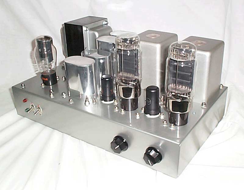
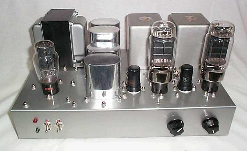
Here's my latest project, another 300B amp based on the WE91A theater amplifier from the 1930s.
This one uses James Universal output transformers that I got for a good price on ebay.
The James transformers outperform the Hammonds I've used in the past, though the
Hammonds aren't slouchy. The power transformer is a Hammond unit, rated at
400-0-400 at 465mA. It weighs in at about 12 pounds. The power supply is filtered by
50uF motor run capacitors paralleled with a 100/100uF at 500V JJ electrolytic. There
was too much hum without the electrolytic. Hum is not audible from 3 feet away from my
Klipsch Cornwalls. The output tubes are KR300Bs, very nice, well built tubes. The
rectifier is a NOS RCA 5Z3. I tried an 83 in this amp and it was necessary to install a
series 100 ohm 10 watt resistor in the power supply to get the voltage down to an
acceptable level. I had problems with the 83s I had. Both of them were damaged in transit, I
think. On one, one side of the filament had come off the little wire hook that supports it at the
top. I was afraid that the filament would eventually sag and short the tube. On the other
83, one side of the plate structure was shifted out of its normal position, causing the
filament to be too close to the plate on that side. The plasma was brighter on that side
as well. It shorted and blew the 1.5A mains fuse. I decided that the 5Z3 is the way
to go. I've never had one fail yet.
The B+ on the first cap is about 410VDC and there's 390VDC on the plates of the
300Bs. They bias at 67VDC on the cathodes, about 23 watts plate dissipation,
very conservative for this tube.
Here's a few more shots for your viewing pleasure.
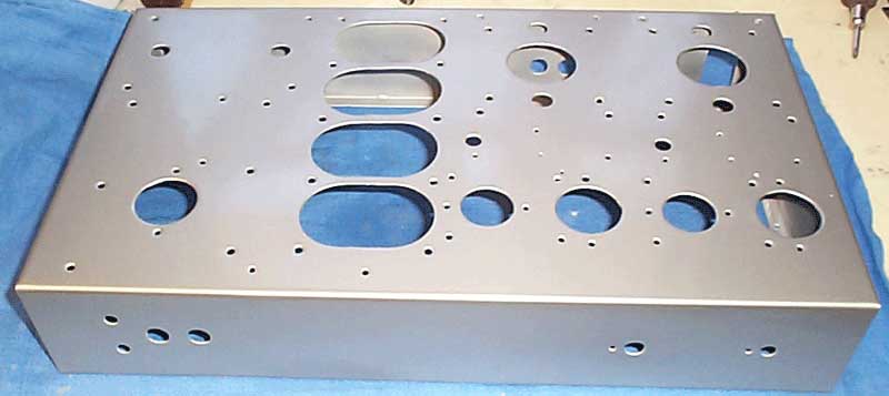
Here's the blank chassis after painting. I used automotive lacquer, custom mixed to match the transformer
color, a metallic silver. Friends have mistaken the chassis for brushed stainless steel. It's a stock
Hammond 17 x 10 x 3 unit. The holes, with the exception of the ovals, are all made with a set of
Unibits and a 1/2" hand drill. The ovals are cut by a machine shop on a mill. Unfortunately, lacquer
is no longer being manufactured in the US due to pollution from the solvent. When
current stock is gone, that's it. It's a great finish and easy to do. The shop where I bought mine put it
in spray cans for me, so I didn't need a sprayer. I sanded between coats with 1000 grit wet
paper and a final 2000 grit before polishing the last coat with rubbing compound
and automotive wax. Powder coating's lots easier and cheaper, but the color choices are
limited to standard colors without a big expense, since the powder is purchased in 50 pound batches.
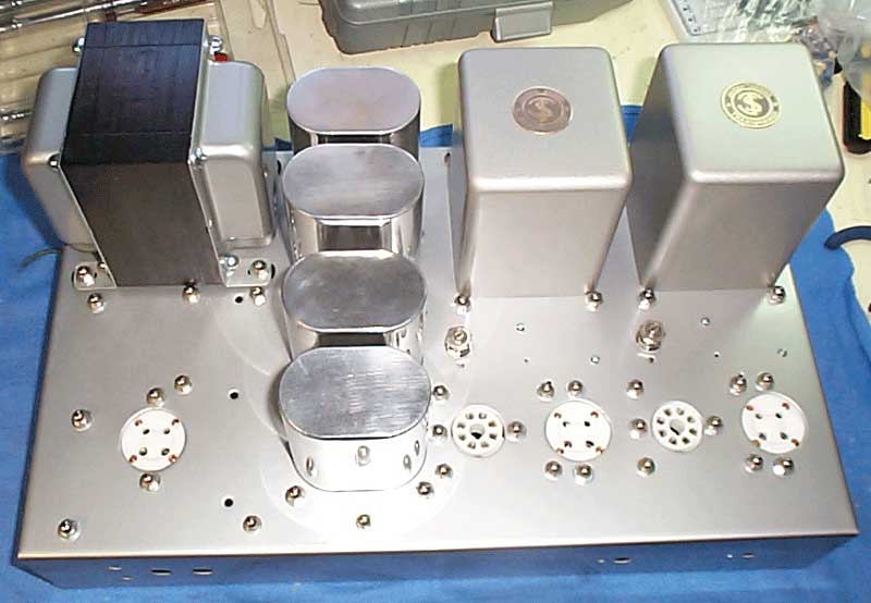
Here's a shot with most of the hardware mounted. The chassis I used had been previously cut to accept
Hammond 16xx series output transformers, but the James units covered the holes nicely. The screw holes
for the Hammonds were used to install an aluminum angle stiffener to support the transformer weight.
You'll see it below.
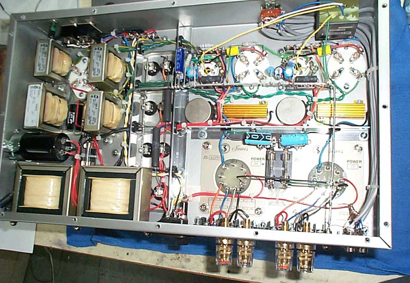
Here's a shot under the hood. You'll see some differences between this amp the others I've built. I learned
a lesson about tubes: Just because it's new doesn't mean it's good. One of the EH300Bs I bought for this
project had an intermittent grid short causing it to unexpectedly go into runaway. It caused a bypass cap
to explode after about 5 minutes of operation. When I replaced the cap and measured the voltage across it
I was shocked <pun intended ;-) > to find 190VDC!!! No wonder the little thing gave it up! I replaced
both bypasses with 160V caps as a safety margin. After this experience, I installed 0.10A
fuses in the ground lines of both 300B cathodes and an additional 0.25A fuse in the ground
of the power transformer secondary. It oughta be safe now! The transformers you see on
the left are Hammond filament transformers and chokes.
Here's a head-on shot.
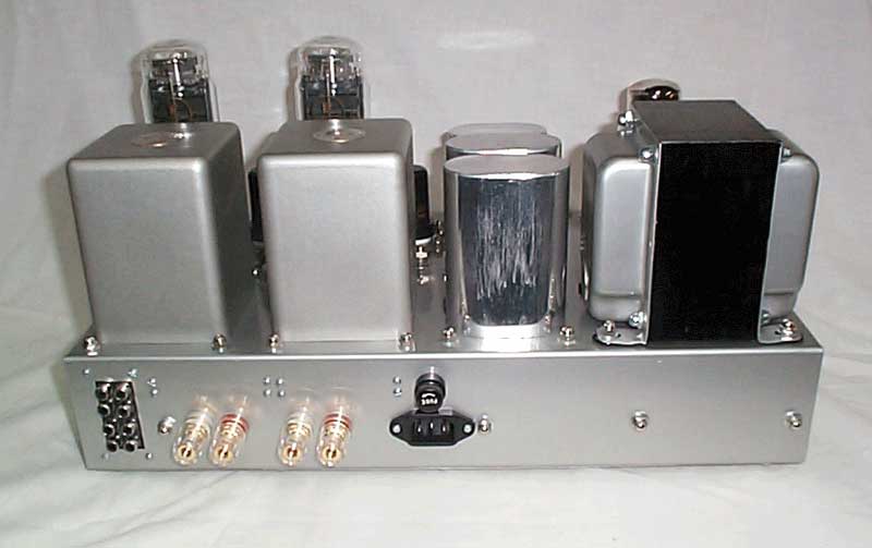
Here's the back of the amp showing the input jacks, speaker binding posts, IEC power connector and fuse.
I must say that this is one of the best amps I've built to date. It produces a very clean 6 watts before clipping,
plenty of power for the Cornwalls.
Here's a link to the article from Sound Practices magazine that inspired me to try this circuit.
WE91A.PDF
Here's a link to the schematic (finally!).
If anyone would like to see more detailed photos or if you have any questions or comments, please
email me at rkoonce@dsityler.com. I always enjoy email from other hobbyists.