built for Larry Terry
August 2007
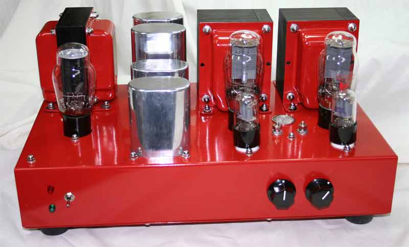
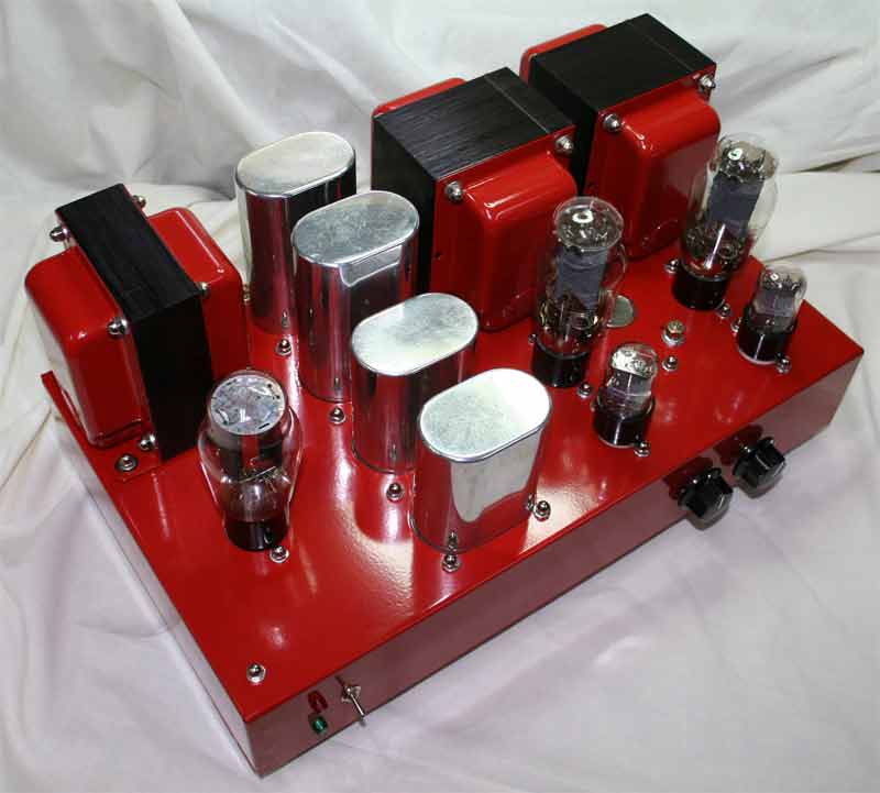
Here's my latest project, a SE2A3 amp which uses Sovtek 2A3s, Sovtek
6SL7s and a NOS 5Z3 rectifier.
This little amp provides great bang for the buck! It plays surprisingly loud
on my Klipsch Cornwalls and it
sounds good on my Electro-Voice Aristocrats as well. As you can see, I'm a
fan of low-power
triodes and efficient speakers.
This amp came about after a long incubation. About six years ago Larry bought
components to build this amp
and never got around to doing anything with them. He had the Hammond transformers
and chassis, tubes,
sockets and most of the resistors and capacitors. After he saw and heard the
300B amp I built for our mutual
friend, Hal
Hudgins, he brought me the parts and asked me to build it for him. I supplied
what he didn't have
and I think the amp turned out nicely.
Here are some shots of the construction process.
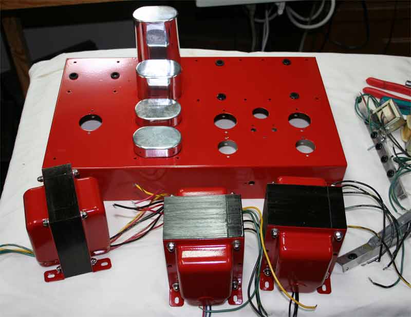
I start with a bare 17 x 10 x 3 Hammond Chassis and make all of the
holes using a variety of tools. The tube socket holes are made
with Greenlee chassis punches. The oval holes for the motor run capacitors
are made with a chassis punch, a nibbling tool and a
Dremel grinding tool. The remainder of the holes are done with a hand drill
and unibits or regular drill bits and files.
This chassis was powder coated. It's a durable finish and is quite easy to
do. Not as much prep work
as for painting. The finish is not quite as polished as what I have done with
paint, but overall it looks very nice.
I use aluminum channel and angle sections to clamp the motor run caps
to the chassis and to serve as mounting brackets for the
filament transformers. I use a separate transformer and bias network for each
2A3 and a 6.3V 1A transformer for the driver
tubes. The center tap of that transformer is connected to a voltage divider
to provide a positive voltage to the heaters.
I also use a separate filament transformer for the 5Z3 and I take the raw
B+ from the center tap.
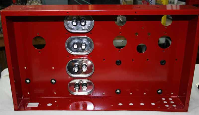
I made additional mounting brackets for terminal strips which you can see
below.
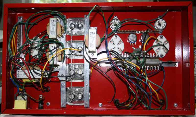
There's sure a rat's nest of wires to tie off before you really start building the amp.
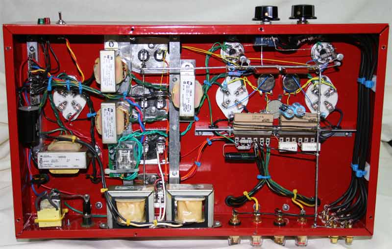
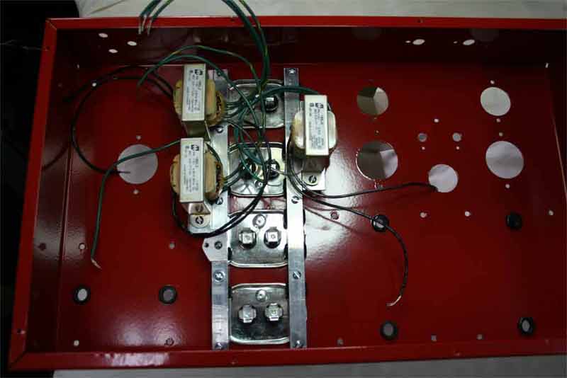
This is what it looks like finished. You can see how I mounted the rectifier
filament transformer on the same
bolts used for one side of the power transformer. I mounted all of the transformers
and chokes using
rubber mounts to avoid any vibrations.
Notice the relay and circuit board just above the left choke. It's
a delay relay made by Sophia Electric and it's
used to delay the application of the B+ voltage until the tube filaments/heaters
are fully warm. This is the second
time I've used this device and it seems pretty simple. If you have a brief
power outage, the time
delay starts again, preventing a rectifier flash and blown fuse.
No boutique parts in this amp, but it sure sounds good. It produces
about 3.5 watts per channel before I can
detect clipping on my scope. It has about 22dB overall gain and is very linear
from 50Hz to well beyond 20KHz.
There are only four electrolytic capacitors in this amp. They are used
for cathode resistor bypass duty. The power supply
is filtered entirely with motor run capacitors. The tall ones are 55uF 440V
units and the shorter ones are 30uF 400V.
I get them from an A/C and heating supply company. I purchase caps with aluminum
cans so that they can be
polished for appearance.
The B+ on the first cap is about 330VDC and there's 305VDC on the plates of
the
2A3s. They bias at 45VDC on the cathodes, just about 15 watts
plate dissipation, fairly conservative for this tube.
Here's a few more shots for your viewing pleasure.
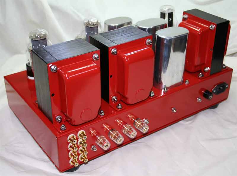
Here's a shot of the rear of the amp showing the input jacks, speaker terminals,
fuse holder (1.5A slow-blow) and IEC
connector. I salvaged this IEC connector from a high-end computer power supply
that had died. It has a built in
filter network and an external cap across the line.
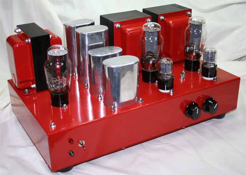
Here's an overhead shot where you can see the ventilation hole between the
power tubes. It's just above where
the cathode resistors are mounted and there's a corresponding opening in the
bottom cover to provide some convective
airflow. I measured the temperature of the cathode resistors after a long
period of operation and they get to a
maximum of about 175° F. Too hot to touch, but not overly stressed. The
ventilation holes were trimmed with
some snap-in screens that I scrounged. They're very nicely made and fit a
1" hole.
Here's a link to the schematic
(finally!).
If anyone would like to see more detailed photos or if you have any questions
or comments, please
email me at rkoonce@dsityler.com.
I always enjoy email from other hobbyists.